
The second project was the removal of the sonar structure attached to the hull.
Note: We’ve revised this part of the blog, as we’ve gotten more information about the sonar from a previous owner. It has not been functional as long as we have had the boat, and likely for several years prior to that time.
When the boat was built in 1941, it had an oscillator blister (we think a primitive sonar unit) attached to the hull about where this sonar structure is. There’s a picture of the oscillator blister in the Youtube video of the construction of the Patton.
At some point, that was removed. To Dan T’s recollection, it had been replaced by the time he was on the boat, prior to the last season (1967). He had never seen the underwater parts, but this was his impression:
I am fairly certain the transducer assembly in your photograph is from the Honeywell Scan Mar Sonar. I do remember it was up forward and I don’t think Jones had one. The unit couldn’t have been very old in 67, as I recall it was all transistorized. Vacuum tubes were the norm back then, fully transistorized equipment was modern and beginning to appear in top of the line equipment . Another indication of age is the type of transducer piezoelectric transducers are modern in 67…I think there were only two components to the Scan Mar the display and the retractable sonar head. I also remember the scanning was done mechanically. I moved the display unit to a location above the radar before we sailed in 67, see attached photographs 029 & 024. The Scan Mar is the display mounted to the overhead above the deck mounted radar display.
Here are some pictures from 1967 provided by Dan:
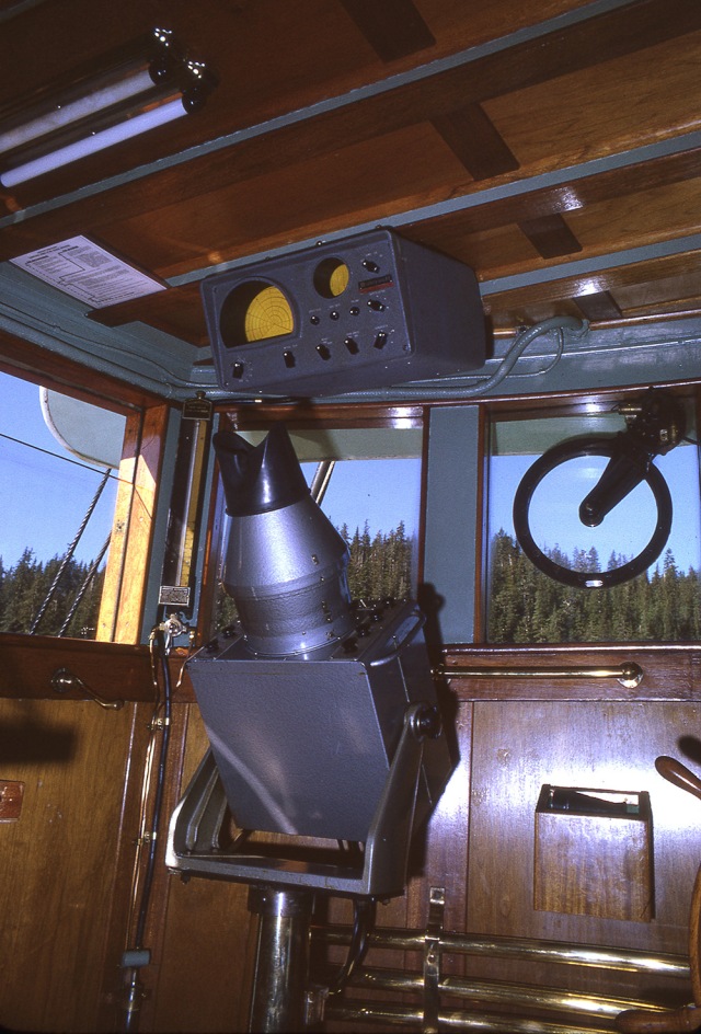
USC&GS Patton – Sonar monitor mounted above the radar
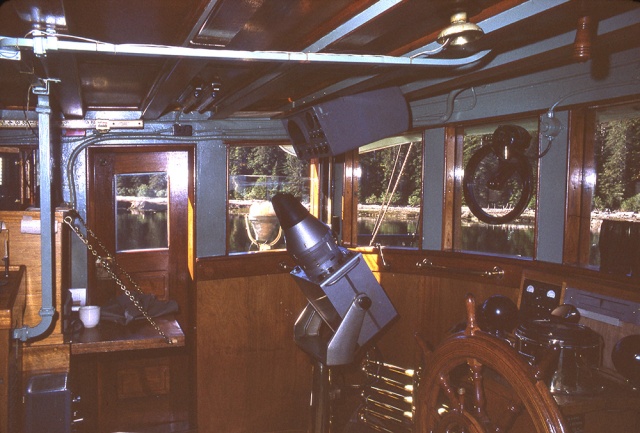
USC&GS Patton 1967 – Side view of sonar monitor
It turns out that the sonar unit we removed was actually installed by a private owner after the boat was decommissioned after the 1967 season (May 1968). The previous owner installed a Wesmar plunging sonar unit, and the steel protective structures were installed at the same time. We opened the grey box that was attached to the transducer and saw the Wesmar trademark. The rest of this blog remains the same.
The external iron framework sticks off the hull a couple of feet just above the keel, a bit aft of the bow, and we were afraid that it might get caught in a cable or a log at some point. On top of that, we have water in the bilge in the section where the unit was located, suggesting that the area around the sonar unit might be leaking.
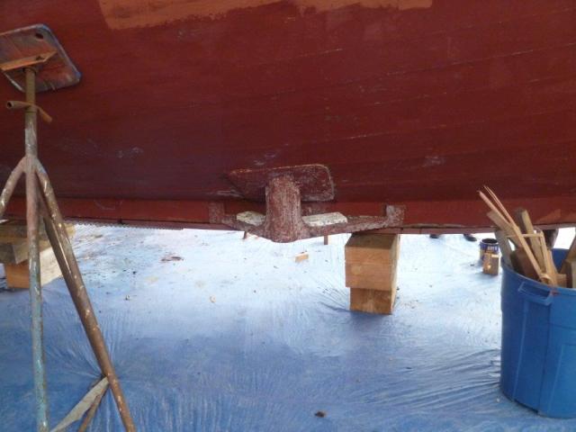
The large metal protuberance off of our hull
We had discussed removing this unit before, but had delayed since the through hull for the unit extended into the garboard plank, which is the lowermost plank on the hull, just above the keel – replacing the garboard plank is expensive and time-consuming. This time we decided to see if we could just remove the unit and plug the hole, rather than replacing the entire plank. We were lucky – the garboard plank was solid, and they were able to fashion and glue a 6 inch round wooden plug and place a heavy plate on the inner side of the hull and a lead plate on the outer side. It sounds easy, but it was a complicated process. Here are the pieces as they came off of the boat (inside bits and outside bits).

Sonar tube after removal – section to the left of the plate was outside the hull, long tubular section to the right of the plate was inside the forward bilge
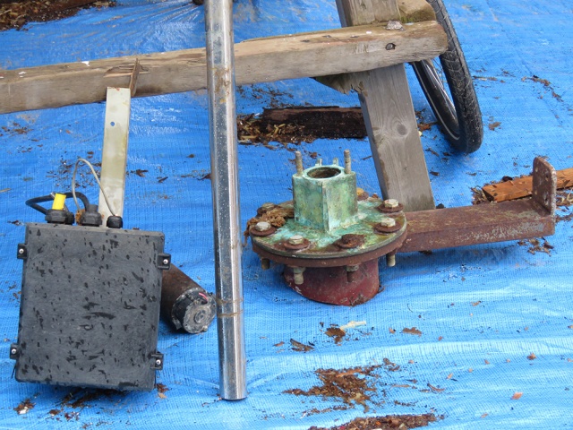
Parts of the sonar unit – electronics and through-hull
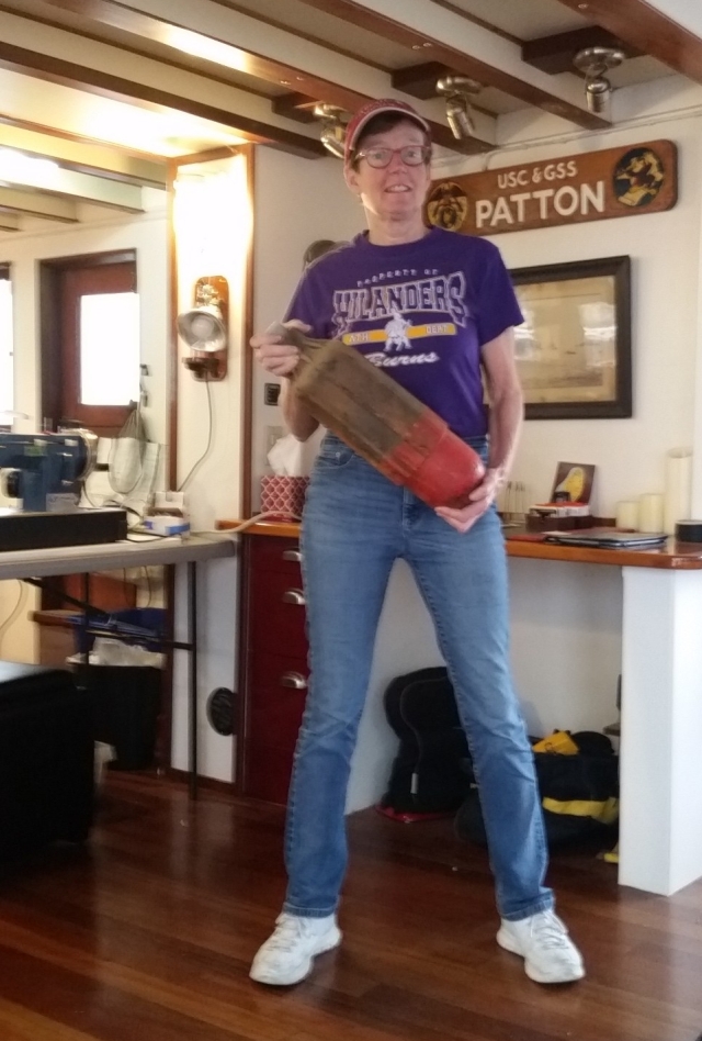
Nancy with the piezoelectric transducer from the sonar
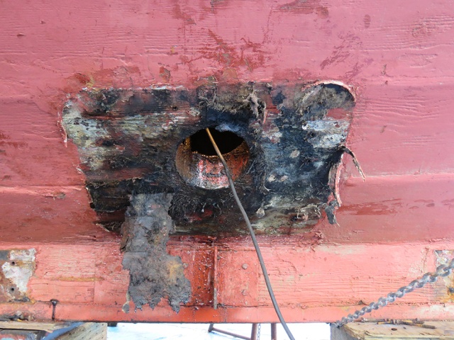
Hole in the hull after removal of the sonar – note that the lower edge extends slightly into the garboard (lowest plank in the hull).
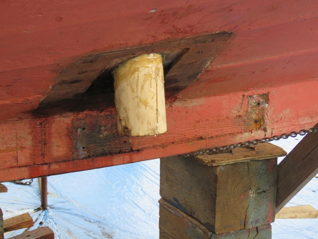
Six inch diameter solid cedar plug glued into the hole
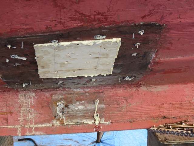
Patch placed (screwed and glued) over the plug for additional security. Below the patch, note the location where the old iron strut attached to the keel


We also worked a bit on the limber holes. Limber holes are a series of small holes in a line that run through the frames near the bottom of the boat. The system allows a small amount of water to move from one compartment of the bilge to another. Originally, there was a brass chain running through the limber holes on either side of the boat. By pulling on the chain from one end of the boat, you could keep the limber hole system open. Over the years, the brass chains rotted and the limber holes plugged with gunk (nasty gunk). We hope to get the limber holes cleared again to prevent water build up in the bilge compartments. The problem is that the limber holes are way deep in the bilges, in the dark, and filled with nasty gunk.
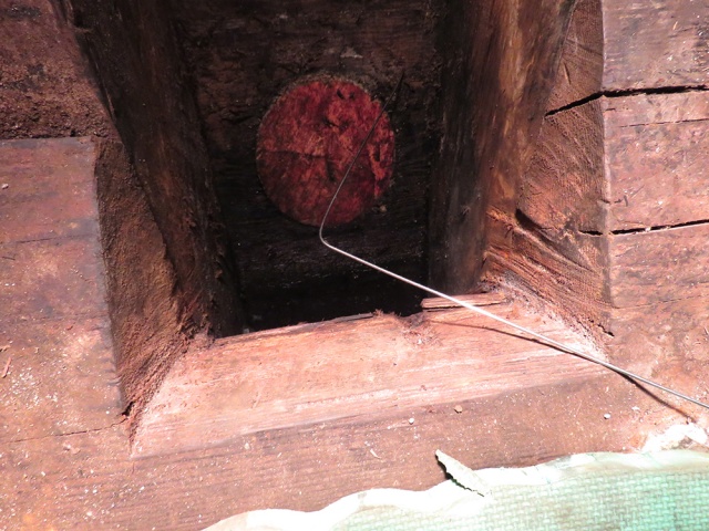
Using a wire to try to clear the limber holes in the bilge compartment with the patched sonar plug

Nancy emerging after a session in the bilge
Unfortunately, we have not yet developed a good method to clear the line of limberholes. Some of them are inaccessible, due to tanks, etc blocking access. We will continue to explore possible options of cleaning them out. Perhaps this would be a good task for when our guests ask if there is anything they can do to help. Perhaps not.

Hi there, Bob Ellsworth here, longest civilian owner of the Triton/Patton with some facts for you on your project. The Patton never had a plunging Sonar until I installed the one you just removed. The survey boys used old technology mounted on the inside of the hull. Most of the actual depth plotting in Alaska was done with a steel cable (buoyed with floats at a set depth) and drug in a semi circle by the Patton and the Jones. Many charts of Alaska today are still noted as, ” Wire dragged to a depth of 5 (or some other number) fathoms” with a date such as June 1947. When they did that if a rock or pinnacle appeared they will mark it as such with a star typically and a note of the depth, say 2 fathoms or whatever.
Once removed the whole mating surface looks fair and lots of black 5200 residue. So your bilge water forward must be coming from somewhere else. We put lot of miles on the old girl with that tube and as you could see there was nary a dent in the tube. Did you remove the deflector ahead or behind the tube? From the photo it’s not possible to tell. If the previous owner did remove them, shame on him as he ran the risk of striking some debris, denting the tube and making the unit inoperable until it could be hauled and a new tube installed. Striking something more substantial than drift (say a rock) might hole the hull and that’s another problem.
The sonar that I installed is/was a Wesmar unit and not a Piezo type as I remember. If you had opened the water proof gray box you would have seen the model and mfgrs detail on the printed circuit board. In addition, in the 60’s the shaft to lower the transducer would have been bronze…The wave guides for the radar also tell me that this is well before 1965. While wave guides hung on for a long time the appearance of these and the fastidious detail to paint and varnish [are hallmarks of the Patton]. Crew that we have had on board always talked about the attention to detail given the Patton by her skippers and crew that the Jones never could equal let alone better.
The varnished plywood veneer between the overhead ceiling frames and ends shows the attention to pimp and shine given the old girl by the crews. The actual overhead was/is tongue and groove Douglas fir or Cedar covered with canvas and paint originally. So the survey boys put that Phillipine Mahogany up there, varnished it and the 1/4 round trims.
You’re sort of correct about the limber holes and chain but not as it applies to the Triton/Patton. The four full (to the main decks) watertight bulkheads prevent any water from running from ahead of the crash bulkhead into the forward section where the Sonar was located or aft into the engine room or the after section or the Lazerette and vice versa. This separation of watertight areas provides each from being affected by the flooding on either side which is why the vessel had/has? a hard piped bilge manifold so that any section can be pumped separately in the event of flooding. My suggestion on how we kept the limber holes freed up is to take a garden hose and install a hose to pipe fitting on the end and at that point switch to 3/8″ ID copper tubing about 4 or 5 feet long. Turn on the main bilge pump, select the section you want to clean and then take your garden hose tubing setup there and start squirting/cleaning the limber holes with it. The copper tubing allows you to bend it enough so you can attack the plugged holes in a more horizontal fashion (it also greatly reduces the black slimy shit that will fly back and all over you).
Last of all I hope that the boat yard did not use glue to put that cedar bung in the sonar tube hole. While epoxy will work, it’s not a mechanical fastening and may not bind well to all that old Wolmanized, salt treated and crud contaminated wood in the planking frames etc. I’m surprised they didn’t cut a Dutchman in the outer plank to mechanically block movement of the plug. Lead is and has been used for hundreds of years to seal something but has zero strength to retain the plug itself which it what you should consider on the next haulout.
I’m pleased of course to see you taking care of the old girl and sharing your experiences. My email is *@*.com and I’m always interested in progress and will answer to the best of my ability any questions you have as time passes. Best regards, Bob Ellsworth
Awesome project with a great outcome. Surprised that protuberance did not snag anything given its dimensions!
Hi Charles,
When I installed the Sonar tube it had deflectors on both the forward side that extended fore and aft of the tube to points ahead of and behind the tube and were bolted thru the keel. This “flying buttress” so to speak prevented anything from fouling the tube. Normally the dipping part is not extended when moving in open water and was most useful entering unknown inlets etc. The bottom of the deflector area was open for painting etc. There was approximately a 1″ gap at the top of them and they extended from the bottom edge of the tube forward about 2′ to where they were fastened to the keel. The sonar transmitter “Bulb” only came down to allow about 1/3 of its’ length it extend beyond the bottom of the tube. The bottom of the tube itself also did not extend as deep as the keel did and the 2″+ thick Ironbark keel shoe was well below the depth of the tube itself,
Best
Bob Ellsworth